How Antennas Work
Posted on 29 February 2024

An antenna is a mechanical structure by which electromagnetic waves are sent out or received.
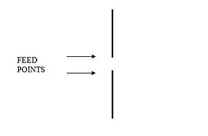
An antenna accomplishes this by being made so that its structure will be resonant at the frequency or frequencies of interest. At the heart of most common antennas is what is known as a dipole. In the simplest form this can be two metal rods, typically one pointed up and the other pointed down with the feed point being between them.
As the name implies there are two poles as seen above. The length of the dipole determines the frequency at which it is resonant. Dipoles are also called “Half Wave Dipoles” by many. This is because when the dipole is approximately one half wave length long in total it will be “Resonant” with the frequency of interest. When a signal is applied to the antenna by a radio it transmits the energy into the air. If the antenna is subjected to a radio wave from another source it converts that energy to an electrical current and that then travels through the feed line to a radio as a received signal. The antenna will perform this for transmission or reception equally.
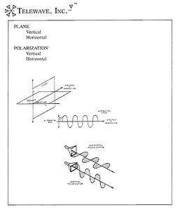
When the dipole is oriented vertically as above it produces or receives signals that are termed vertically polarized. The transmitted radio wave that leaves the dipole is a wave that oscillates up and down. If the dipole was in the horizontal plane the signal would oscillate side to side and would be termed horizontally polarized.
The graphic below shows this clearly.
As the name implies there are two poles as seen above. The length of the dipole determines the frequency at which it is resonant. Dipoles are also called “Half Wave Dipoles” by many. This is because when the dipole is approximately one half wavelength long in total it will be “Resonant” with the frequency of interest. When a signal is applied to the antenna by a radio it transmits the energy into the air. If the antenna is subjected to a radio wave from another source it converts that energy to an electrical current and that then travels through the feed line to a radio as a received signal. The antenna will perform this for transmission or reception equally.
When the dipole is oriented vertically as above it produces or receives signals that are termed vertically polarized. The transmitted radio wave that leaves the dipole is a wave that oscillates up and down. If the dipole was in the horizontal plane the signal would oscillate side to side and would be termed horizontally polarized.
The graphic below shows this clearly.
If a vertically polarized antenna has a horizontally polarized signal arrive from another antenna it will not receive the signal at a sufficient strength for the receive radio to be able to use it. And the reverse is also true that a vertically polarized transmitted signal from our system would not be useable to a horizontal remote receiving system.
Frequency
Looking at the graphic above we see a depiction of what is called a Sine Wave. This is the basis of all radio waves. We see that the signal starts out going up, peaks and then goes down, peaks again and then it rises to the center line where it started. This is one cycle; from zero to plus, then to minus and back to zero. This can vary in length of course, and this length and the time it takes to make one cycle we use to determine the frequency. The frequency of the most common radio systems is measured in Mega Hertz (MHz) which is millions of cycles per second. Radio waves travel through free space (air) virtually at the speed of light, so we can then determine the Wave Length. For instance, a 150 MHz signal will have a WL of 78.7 inches. A 450 MHz signal will have a WL of 26.2 inches.
Antenna designers use these numbers when designing antennas to make sure the antenna will be resonant at the frequency of interest. As we see above, the lower frequency has a longer WL and the higher frequency has a shorter WL. Hence the antenna of a lower frequency will be larger than an antenna for the higher frequency. A common dipole used to operate at 150 MHz should be about one half a WL tall, so we would expect it to be 39 inches tall and a 450 MHz dipole would be approximately 13 inches tall.
It is important to note that a 150 MHz antenna will not be affected by signals at 800 MHz as it is not resonant at the higher frequency.
You may have seen a demonstration where a soprano sings a particular note and is able to cause a crystal glass to shatter. This happens because the note and the glass are resonant. The audible waves cause the glass to vibrate to the point of destruction.
Antenna Types
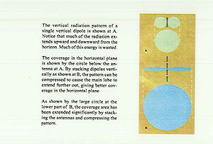
There are many types of antennas. The basic reason for the many different types is that they produce different shapes of signals called patterns. The basic dipole produces a signal as seen below at A.
The depiction is what we would see if we could see radio waves being transmitted. The upper portion at A is what the pattern would look like if we were standing off to the side and we could see the energy in cross section. Below that still at A the circle is what it would look like if we were directly above the dipole looking down.
What happens when we make an antenna that has several dipoles arranged one above the others in what is called an array, is seen at B below. We see that the cross section has become flattened and that the view from above shows the circle has gotten larger in diameter. So, standing several dipoles up one above the other changes both the Vertical (as seen from the side) and the Horizontal (as seen from above) patterns. The larger diameter of the circle at B is intended to demonstrate that it will be able to transmit and receive at a greater distance than the single dipole would.
The above shows that we can change the way antennas distribute the energy that they send out into the air.
This leads us to an unfortunate term that is widely used when discussing antennas and that term is GAIN. The word implies that we are going to get more of something. The truth is that we do not get more. The total amount of energy radiated by the single dipole is the same as that radiated by the four bay array if they are fed equal signals. The energy in the four bay dipole array has been distributed differently is all that has happened. The vertical pattern has been compressed and because of this the signal level that we would measure at the horizon from the single dipole would be found to be the same for the four-bay array at a much further distance. Yes, we have been able to get the four-bay dipole array to communicate to a further distance than the single dipole, but there is still the same amount of total energy emitted by both antennas. So, Gain really isn’t Gain in power, it is just compressing the signal in ways that provide a pattern that suits our needs better.
The various types of antennas are all based on the simple dipole, and it is the basis of all common antennas. Depending upon what we want the pattern to do suggests the type of antenna that we select. We need to consider where we need a signal to be placed from a given location where the antenna is mounted.
When discussing antennas we often talk about Radio Frequency (RF) energy. This is measured in Deci Bells (dB), honouring Alexander Graham Bell. The term dB by itself is not a usable term. It has to be referenced to something. In antennas, it is either dBd, where we compare a signal level to a dipole or it is dBi when referencing a signal level to an isotropic radiator. An isotropic radiator is an impossible antenna to make as it is defined a single point in space that radiates equally in all directions. This dBi is useful in some engineering efforts but isn’t much help with real antenna measurements. The difference is that one dBd is equal to 2.14 dBi and is a mathematically calculated value.
Discussing antenna patterns usually involves a reference to the antenna’s beam width. This can be measured for both the vertical and the horizontal beams unless the subject happens to be a collinear antenna where the horizontal beam is circular. We’ll come back to that antenna later.
The beam width is defined as the included angle between the points where the power level has dropped to one-half of the peak gain value. The increase of signal level to a value of double is 3 dB, and if it is half it would be -3dB. So, you may hear the term half power points in reference to describing the beam width that an antenna produces.
In the example below, which is an example of the vertical, or E-Plane pattern of a Yagi-type antenna you can see the half power points marked on the pattern with a dash.
That particular antenna produced 10.52 dBd of gain, so the half-power points would measure 7.52 dBd, and the included angle between the dashes is about 44 degrees.